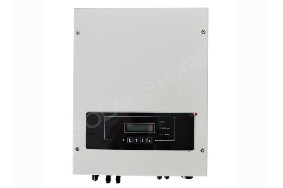
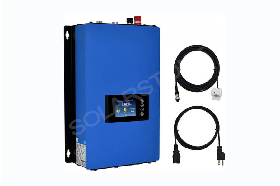
In China, photovoltaic power stations have been constructed in batches since 2010. At this time, there are few domestic series inverter suppliers and the technology is immature, while the price of foreign products is very high.
The system cost of using a series inverter in large ground power stations is much higher than that of using the centralized inverter, which makes a centralized inverter the first choice for ground power stations, As a result, the centralized inverter occupies an absolutely dominant position in China’s ground power plants. The majority of photovoltaic practitioners are not familiar with a series inverter, and there are still misunderstandings in understanding, mainly including the following points:
Misunderstanding 1: there are a large number of series inverter machines in-ground power stations, and the maintenance is more complex and difficult than centralized
This view is actually caused by a lack of understanding of centralized and serial maintenance methods.
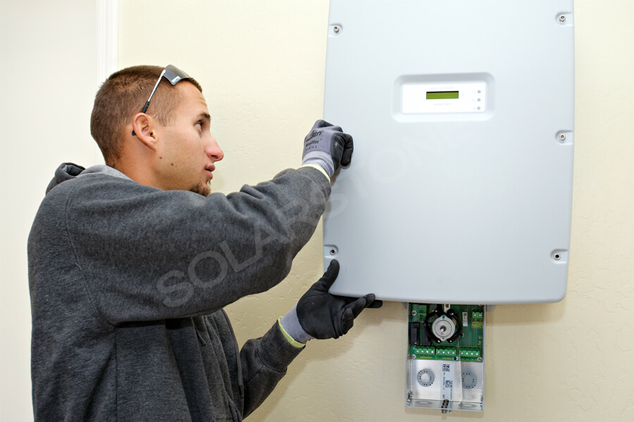
Generally, the maintenance of the series inverter is directly replaced by the operation and maintenance personnel of the power station, with low skill requirements; The centralized maintenance requires the technicians of the manufacturer to come to the site, which requires very high skills. The advantages of series maintenance are very obvious, especially in remote areas or overseas.
An obvious fact can prove that few responsible inverter manufacturers dare to sell centralized inverters abroad, but almost all manufacturers dare to sell series inverters abroad.
The reason is very clear. The maintenance cost abroad is too high and the cost of maintenance personnel is expensive.
Spare parts are also a problem. It is not easy to keep them locally and it is not feasible to carry them with you. When they arrive at the site, they are found to be inappropriate and have to be reissued from China, which will not only delay time but also cause claims from the power station owner, which will become a nightmare for the inverter manufacturer.
If the customer wants to sign a 20-year maintenance contract with the inverter manufacturer, it may not be a good thing for the inverter manufacturer: the probability of problems with the centralized inverter in the 20-year maintenance cycle is 100%, and the money earned from selling the equipment will be compensated for several times.
This also explains why the suppliers of centralized inverters in various countries are almost all local manufacturers. On the one hand, local manufacturers are more familiar with the domestic market, on the other hand, it is difficult to guarantee the services of foreign manufacturers.
From the impact of fault on the power station, the series inverter also has obvious advantages: assuming that the annual failure rate of both series inverter and centralized inverter is 1%, 1MW power station has 2 centralized inverters and 40 series inverters.
The average repair time of series inverter is 2 hours and that of the centralized inverter is 12 hours (considering that the response time of each manufacturer is different, The actual repair time of centralized inverter may be much longer), and the loss of power generation caused by the failure of the series inverter is only 1 / 6 of that of the centralized inverter, as shown in the table below. The root cause is the difference in maintenance methods.
For a long time, the maintenance advantages of series inverters are more obvious. For example, to replace the string type small machine 10 years ago with the current string type small machine, there is little difference between the DC side and AC side cables, and the communication protocol is slightly different.
If the terminal cable is not suitable, it can be realized by adding cable transfer. However, the current string type inverter is much cheaper than the products 10 years ago, and it is easier to replace.
If the centralized inverter of the same manufacturer is used to replace the machine 10 years ago because the general production time of the product is no more than 5 years, it will be found that all circuit boards, inductors and other components are not suitable, and the inventory of components can not exceed 5 years, so the replacement of components is very expensive and difficult to find.
It is more realistic and cheaper to replace each other with series inverters, while the replacement of centralized inverter is no different from the reconstruction of the power station, which is time-consuming and laborious. The construction of domestic centralized power stations began only after 2010, and the maintenance problems are not prominent, and the subsequent maintenance problems will be gradually exposed.
Misunderstanding 2: with a large number of series inverter machines, the harmonics of the power station will become larger
Harmonic refers to the voltage or current component whose frequency is an integral multiple of the fundamental wave contained in electricity. Generally, it refers to the Fourier decomposition of periodic nonsinusoidal current and deducting the current component at other frequency points other than the fundamental wave.
Harmonic current will produce harmonic voltage drop on the short-circuit impedance of the power grid and affect the voltage output waveform (user terminal voltage = power grid stable voltage – harmonic voltage drop).
The harmonic of power grid mainly comes from three aspects: first, the quality of power generation source is not high, resulting in harmonic; Second, the transmission and distribution system generates harmonics; Third, the harmonics generated by electrical equipment, of which the most harmonics are generated by electrical equipment.
In electrical equipment, the harmonics generated by the rectifier account for nearly 40% of all harmonics, which is the largest harmonic source.
The inverter is a power generation equipment, which does not control the output voltage. Relying on the grid voltage, it only injects the current into the grid. This working model has little impact on the grid voltage harmonic (except if the inverter causes the resonance of the grid).
Therefore, when measuring the power quality of the parallel grid of the photovoltaic power station, when the grid voltage harmonics can meet the requirement of 5%, the focus is on the current harmonic output by the inverter. The current harmonics of an inverter is mainly related to the following factors:
(1) Output voltage waveform quality: in the inverter control algorithm, the output voltage is a sine wave. When the output PWM wave modulated by the inverter is distorted, the output harmonic and control effect of the inverter will be affected.
Increasing the switching frequency and the number of output PWM levels can help to reduce the distortion rate of PWM waveform. The three-level series inverter with a high switching frequency has more advantages than the two-level centralized inverter with a low switching frequency.
(2) Software control bandwidth: the higher the switching frequency of the inverter, the wider the control bandwidth, and the more sufficient suppression of current harmonics in a wide range. In order to ensure stability, the control bandwidth of the inverter is usually about 1 / 10 of the switching frequency;
The switching frequency of series inverter (about 16KHz) is much higher than that of the centralized inverter (3kHz for two-level inverter and 8K for three-level inverter), with wider control bandwidth and stronger control ability for low-order harmonics.
The control frequency is high, so the power grid harmonic can be detected in the control loop, and the suppression program for low-frequency harmonic can be added, so that the output current harmonic of the inverter can do better than the voltage harmonic of the power grid.
(3) Performance of grid-connected filter: the high-frequency component of output current beyond the control bandwidth needs to be filtered by the filter. LCL filter is generally used for series inverter, which has the advantages of strong high-frequency harmonic attenuation ability and little influence by grid-connected impedance.
(4) Parallel harmonic cancellation capability: one square array and multiple series inverters are different from the step-up transformer, and the line impedance will be different. The line impedance will equivalent change the inductance of L2 in the grid-connected LCL filter, and different filter parameters will change the phase of harmonics.
When multiple series inverters work in parallel, the harmonic components will be partially eliminated from each other due to the phase difference, reducing the harmonic value of the whole system.
From the above four points, it can be seen that the output current harmonics of series inverter is not worse than that of a centralized inverter in principle. Due to its higher working frequency, a harmonic suppression algorithm can be added to the algorithm to ensure that the output current harmonic is not disturbed by the power grid harmonic, which is more advantageous than the centralized inverter.
Misunderstanding 3: a large number of series inverters are connected in parallel, which is more likely to cause resonance and lead to system instability
The inverter multi-machine parallel system consists of a photovoltaic cell array, multiple inverters, transmission and distribution equipment and a power grid. The inverter and power transmission and distribution equipment have strong nonlinearity.
The photovoltaic cell array at the power input and the output power grid may also be greatly disturbed, and the whole system is very complex.
If the design is unreasonable, there may be oscillation between multiple inverters and between inverters and power grid, resulting in inverter protection disconnection, and even personal and property losses. There are many reasons for resonance, which are not directly related to the number of equipment.
For example, from the perspective of the distribution network, residents in the distribution network have a large number of electrical equipment with different power levels, but the resonance is not obvious. On the contrary, there are a small number of high-power equipment in the factory, which is more likely to cause resonance.
Common parallel resonance in the grid-connected inverters can be divided into two cases:
In the first case, when multiple inverters work in parallel, their output grid-connected terminal has a common impedance, which leads to multi-machine resonance between parallel inverters.
In the parallel system, when the output current of one inverter contains harmonics, the harmonic component will produce harmonic voltage drop on the circuit and affect the grid-connected terminal voltage of other inverters in parallel. When the voltage harmonic is close to the control frequency of the inverter, it may lead to multi-machine parallel resonance.
This resonance is common in inverter parallel systems with low working frequency. The working frequency of the centralized inverter is 3 ~ 8kHz, while the working frequency of the series inverter is higher than 16KHz. Therefore, parallel centralized inverter is more prone to this resonance.
In the second case, the inverter port has a filter capacitor, which forms an LC network with the leakage inductance of the transformer. Resonance will occur when the high-order harmonic contained in the output current of the inverter is exactly the same as the resonant frequency of the LC network.
At this time, if the power grid also contains high-order harmonics of the same frequency, the oscillation will intensify, resulting in the oscillation of power grid voltage.
This resonance is difficult to encounter in large-scale ground power stations with a clean power grid, while it may occur in distributed low-voltage grid connections due to complex local load and large content of high-order harmonics in the power grid.
In essence, these two resonances are caused by high-order harmonics in the output of the inverter itself. The fundamental method to suppress resonance is to improve the control of the inverter and the design of LC filter to ensure that the output side of the inverter does not contain high-frequency harmonics.
For large power stations with series inverters, generally, 1 ~ 2MW is designed to form a grid connection unit, which is connected to the grid through an isolation transformer. The isolation transformer will play a good decoupling role between MW units to ensure that there will be no phase impact between MW units.
In the MW unit, when multiple machines are connected in parallel, due to the high switching frequency of the series inverter, which generally reaches more than 16KHz, the control bandwidth is also relatively wide, which generally reaches about 2KHz, while the harmonic component in the power grid generally does not exceed 2KHz.
Within the control bandwidth of the series inverter, the series inverter can add these harmonic suppression algorithms to the control loop, Making the inverter unresponsive to the harmonics of these frequencies can effectively prevent the occurrence of resonance, so as to ensure the stability of the system.
Misunderstanding 4: the low voltage ride through the performance of a series inverter is worse than that of a centralized inverter
The so-called low through / zero through means that the inverter detects that the grid voltage falls behind, keeps it from being disconnected from the grid for a short time and outputs reactive power to the grid to support the recovery of the grid as soon as possible.
During zero crossing, the grid voltage does not completely fall to zero. In the standard, it is considered that if the grid voltage falls below 5%, it is zero crossings, because the inverter also needs to detect the phase of the grid before it can send reactive power to support the grid.
The key point of the inverter’s response to low penetration is that the inverter can detect the drop of grid voltage in time, and then make a corresponding response according to the internal algorithm. In a grid-connected unit, the impedance of the AC cable is not large, and the inverter can detect and respond to the grid drop-in time.
Therefore, the low penetration is completely the independent behavior of the inverter, and there is no need for any linkage between the inverters. The low penetration characteristics of the power station are not necessarily related to the number of inverters.
The German medium voltage grid connection standard BDEW puts forward the requirements of a low-voltage ride-through for the first time in the industry. The evaluation of inverter low-voltage ride through in this standard is mainly to conduct single machine test, and then conduct modeling and simulation according to the single machine test results.
The low penetration characteristics of multi-machine parallel are obtained through software simulation. In the process of parallel simulation, there will be no mutual interference between multiple inverters, resulting in poor low penetration performance.
Misunderstanding 5: if multiple series inverters interfere with each other, the island cannot be protected
Islanding means that when the power grid trips and interrupts the power supply due to faults, accidents, natural factors, or power outage maintenance, the photovoltaic grid-connected inverter fails to immediately detect the power outage state and cuts itself off from the municipal power network, but still continues to transmit a certain proportion of electric energy to the power grid, the solar grid-connected power generation system and the surrounding loads form a self-sufficient power supply island that can not be mastered by the power company.
It can be seen from the definition that there are two conditions for the grid-connected photovoltaic inverter to form an island: the inverter system is separated from the power grid; The output power of the inverter matches the local load, resulting in the continuous output of the output voltage, thus forming a power supply island operation.
The anti-islanding protection scheme of the inverter is divided into an active anti-islanding protection scheme and a passive anti-islanding protection scheme. The passive scheme detects the islanding effect by detecting the abnormal voltage or frequency at the AC output of the inverter. In this scheme, each inverter detects the power grid, and multiple inverters will not interfere with each other.
The active scheme intentionally introduces disturbance signals to monitor the corresponding changes of voltage, frequency and impedance in the system to determine the existence of a power grid. Active anti-islanding protection schemes mainly include frequency offset, impedance change caused by current pulse injection, power line carrier communication, etc.
In the active islanding scheme, if there are Inverters from different manufacturers in a grid-connected unit, the active islanding scheme may be affected due to the inconsistent direction of disturbance signals.
In the process of standard certification, the anti-islanding test is very strict. The test organization especially constructs an LC resonant network with the resonant frequency of 50Hz to test the islanding, so as to ensure that the inverter can carry out islanding protection under these extreme conditions.
In order to meet the requirements of the standard, passive anti-islanding is not enough, and the active anti-islanding scheme must be added.
In the real grid connection, the LC resonant network with a resonant frequency of just 50Hz is almost impossible to encounter. The inverter can achieve the purpose of protection through passive anti-islanding means such as voltage and frequency detection.
A research institute in the Netherlands released a report that although a large number of power stations in Europe use series inverters, and the active islanding schemes of Inverters from different manufacturers may be inconsistent, the protection can be realized only by the passive islanding scheme, and the passive islanding scheme will not interfere with each other, so there are no problems caused by islanding in actual power stations.


