Introduction
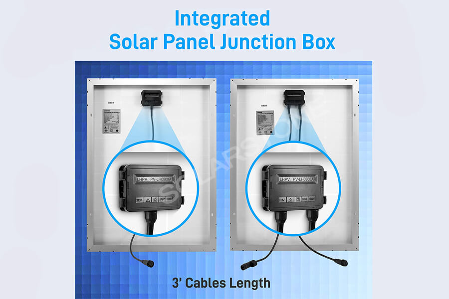
The junction box is a connector between the solar array and the charging control device, it is an important part of the solar panel. It is a cross-domain comprehensive design combining electrical design, mechanical design, and material science. It provides users with a combination connection scheme of solar panels.
As a kind of solar panel connector, the main function of the solar photovoltaic junction box is to export the power generated by the solar cell module through the cable. Due to the particularity of the use of solar cells and their expensive value, the solar photovoltaic junction box must be specially designed to meet the requirements of the use of solar panels.
1. Function
The photovoltaic junction box has two main functions: the basic function is to connect the photovoltaic panel and the load, to lead out the current generated by the photovoltaic panel, and generate power. The additional function is to protect the outgoing line from the hot spot effect.
1.1 Connection
As a connector, the junction box serves as a bridge between solar panels and inverters. Inside the junction box, the current generated by the solar panel is led out and led into the electrical equipment through the terminals and connectors.
To reduce the power loss of the junction box to the board as much as possible, the conductive material used in the junction box should have a small resistance, and the contact resistance with the outgoing line of the bus bar should be small.
1.2 Protection
The protection function of the junction box includes three parts: one is to prevent the hot spot effect through the bypass diode to protect the cell and solar panel; Second, waterproof and fireproof are designed by sealing with special materials; The third is to reduce the working temperature of the junction box and the temperature of the bypass diode through the special heat dissipation design, to reduce the loss of the leakage current to the solar panel power.

2. Character
2.1 weather resistance
Weatherability refers to: when materials are used outdoors, they are subjected to the test of climate, such as the damage caused by light, cold and hot, wind and rain. The exposed parts of the junction box are the box body, box cover, and connector (PC). They are all made of materials with strong weather resistance. At present, the most commonly used material is PPO (polyphenylene oxide), which is one of the five general engineering plastics in the world. It has the advantages of high rigidity, high heat resistance, fire resistance, high strength, and excellent electrical performance. In addition, polyether also has the advantages of wear resistance, nontoxicity, and pollution resistance.
2.2 High temperature and humidity resistance
The working environment of solar panels is very bad, some of them work in tropical areas, and the daily average temperature is very high; Some working temperature is very low, such as high altitude area, high latitude area; In some places, the temperature difference between day and night is very large, such as in desert areas. Therefore, the junction box is required to have excellent high-temperature resistance and low-temperature resistance.
2.3 UV resistance
Ultraviolet radiation has certain damage to plastic products, especially in the plateau where the air is thin and the ultraviolet irradiance is very high.

2.4 Flame retardancy
Flame retardancy refers to the property that the material has or has been treated to delay the flame spread.
The flame retardant grade increases gradually from Hb, V-2, V-1 to V-0: the lowest flame retardant grade in Hb: UL94 and CSA c22.2 no 0.17. It is required that the burning rate of 3 to 13 mm thick samples should be less than 40 mm / min; For samples, less than 3 mm thick, the burning rate is less than 70 mm / min; Or go out in front of the 100 mm mark. V-2: the flame is extinguished within 60 seconds after two 10 second combustion tests. There can be combustibles falling. V-1: the flame is extinguished within 60 seconds after two 10 second combustion tests. No combustibles should fall. V-0: the flame is extinguished within 30 seconds after two 10 second combustion tests. No combustibles should fall.
2.5 Waterproof and dustproof
Standard: GB 4208 2008 “enclosure protection level (IP code)” in the provisions of the dust-proof and waterproof grade IP grade, general junction box waterproof and dustproof grade IP65, IP67.
2.6 Heat dissipation
The diode and ambient temperature will increase the temperature in the junction box. When the diode is on, it will generate heat. At the same time, because of the contact resistance between the diode and the terminal, it will also generate heat. In addition, the increase of ambient temperature will also increase the internal temperature of the junction box.
The components easily affected by high temperature in the junction box are sealing rings and diodes. The high temperature will accelerate the aging speed of the sealing ring and affect the sealing performance of the junction box; There is a reverse current in the diode, and the reverse current will double when the temperature increases by 10 ℃. The reverse current will reduce the current generated by the board and affect the power of the board. So, the junction box must have excellent heat dissipation.
The common heat dissipation design is to install a heat sink. However, the installation of a heat sink does not completely solve the problem of heat dissipation. If the heat sink is installed in the junction box, the temperature of the diode will be reduced temporarily, but the temperature of the junction box will still rise, which will affect the service life of the rubber seal ring; If it is installed outside the box, on the one hand, it will affect the overall sealing of the junction box, and it will also easily cause the heat sink to be corroded.

3. Classification
There are mainly two types of junction boxes: ordinary and potted.
Ordinary junction box is sealed with silica-gel sealing ring, while rubber filled junction box is filled with two-component silica gel. An ordinary junction box is used earlier and easy to operate, but the sealing ring is easy to aging when it is used for a long time. The operation of the potting junction box is complex (need to fill two-component silica gel, and cure), but the sealing effect is good, aging resistance, can ensure the long-term effective sealing of junction box, and the price is a little cheaper.
There are other classifications of junction boxes, according to power and connector, and also according to diode working current.

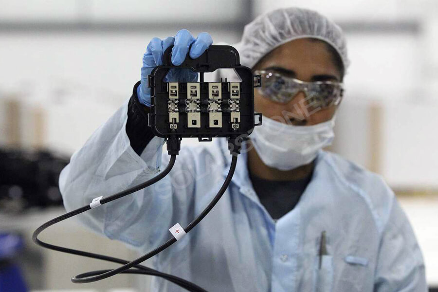
4. Composition
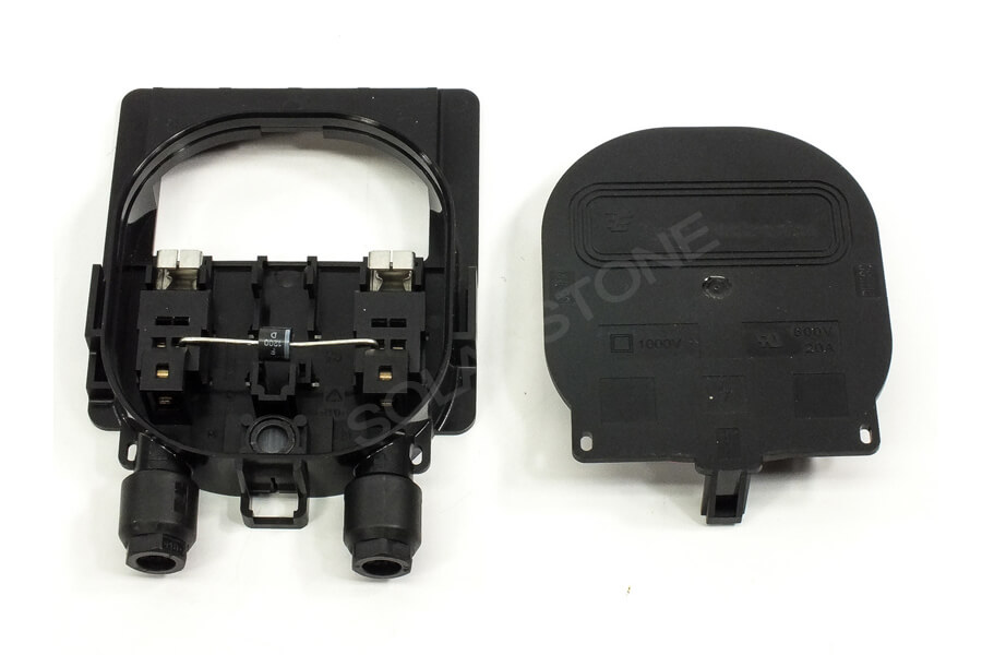
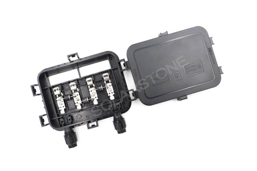
The junction box consist by box body, box cover, connector, terminal, diode, etc. Some junction box manufacturers have designed heat sinks to enhance the temperature distribution in the box, while some junction box manufacturers have designed other details, but the overall structure has not changed.
4.1 Box body
The box body is the main part of the junction box, with built-in terminals and diodes, external connectors, and box cover. It is the frame part of the junction box and bears most of the weather resistance requirements. The box body is usually made of PPO (polyphenylene oxide), which is one of the five general engineering plastics in the world. It has the advantages of high rigidity, high heat resistance, fire resistance, high strength, and excellent electrical performance. In addition, polyether also has the advantages of wear resistance, nontoxicity, and pollution resistance.
4.2 Box cover
The box cover can seal the box body and prevent water, dust, and pollution. The tightness is mainly reflected in the built-in rubber sealing ring to prevent air and moisture from entering the junction box. Some manufacturers set a small hole in the center of the box cover. A dialysis membrane is installed in the air. The membrane is breathable and impermeable, and there is no water infiltration three meters below the water. It plays a very good role in heat dissipation and sealing.
The box body and cover are generally made of materials with good weather resistance by injection molding, with good elasticity, temperature impact resistance, and aging resistance.
4.3 Connector
The connector connects the terminal and external electrical equipment, such as inverter, controller, etc. The connector is made of PC (polycarbonate), but PC is easy to be corroded by many substances. The aging of junction box is mainly reflected in that the connector is easy to be corroded and the plastic nut is easy to crack under low-temperature impact. Therefore, the service life of the junction box is the life of the connector.

4.4 Terminals
There are 2, 3, 4, 5, 6, and other specifications for the outgoing line and connector of the terminal board. The width of the terminal itself is 2.5, 4, 6 mm according to the different outgoing lines. The terminal spacing is also different for the terminal boxes of different manufacturers.
There are two ways of contact between the terminal and the outgoing line: one is physical contact type such as pressing or tightening type, and the other is welding type.
4.5 Diodes
The diode in the PV junction box is used as a bypass diode to prevent the hot spot effect and protect the solar panel.
When the solar panel works normally, the bypass diode is in the cut-off state, and there is a reverse current, that is, dark current, which is generally less than 0.2 microampere. Dark current will reduce the current generated by solar panels, although the amplitude is very small.
Ideally, every solar cell should be connected with a bypass diode. However, due to the influence of the price and cost of the bypass diode, dark current loss, and voltage drop under working conditions, it is very uneconomical. In addition, the position of the solar panels is relatively concentrated. Don’t forget to provide sufficient heat dissipation conditions after diodes connecting.
Therefore, it is generally reasonable to use a bypass diode to protect multiple interconnected solar cells. This can reduce the production cost of solar panels, but it will also adversely affect their performance. If the output power of one solar cell in a series of solar cells decreases. Then this series of solar cells, including those working normally, will be isolated from the whole solar panel system due to the bypass diode. As a result, the output power of the whole solar panel will decrease too much due to the failure of one solar panel.
In addition to the above problems, the connection between the bypass diode and its adjacent bypass diode must be considered carefully. These connections are affected by some stresses, which are the product of periodic changes in mechanical load and temperature. Therefore, in the long-term use of solar panels, the above connection may fail due to fatigue, which makes the solar panels abnormal.
4.5.1 Hot spot effect
In the structure of solar panels, individual solar cells are connected in series, which is called series connection to achieve higher system voltage. Once one of the solar cells is blocked (for example, branches or antennas, etc.), the affected solar cells will no longer work as power sources but become energy consumers. Other unshielded solar cells will continue to transfer current through them, causing high energy loss, “hot spots” will appear, and even solar cells will be damaged.
To avoid this problem, bypass diodes are connected in parallel to one or several solar cells connected in series. The bypass current bypasses the shielded solar cell and passes through the diode.
When the solar cell is working normally, the bypass diode turns off in the reverse direction, which does not affect the circuit; If there is an abnormal solar cell in parallel with the bypass diode, the current of the whole line will be determined by the minimum current solar cell, and the current will be determined by the shielding area of the solar cell. If the reverse bias voltage is higher than the minimum voltage of the solar cell, the bypass diode will turn on, Abnormal operation solar cell is short-circuited.
It can be seen that the hot spot is the solar panel heating or local heating, and the solar panel at the hot spot is damaged, which reduces the power output of the solar panel, and even leads to the waste report of the solar panel, which seriously reduces the service life of the solar panel, and causes hidden dangers to the safety of power generation of the power station. Heat accumulation leads to poor or damaged solar panels.

For the formation of solar panel hot spots, the main external factor is that the solar panel is partially or partially covered by obstructions. The common obstructions are leaves, dust, clouds, animals and animal feces, snow, etc; The internal resistance of solar cells is related to the reverse current of solar cells. This conclusion can be analyzed from the actual equivalent circuit of solar cells. The load is connected in series with the internal resistance of the solar cell
If I = IPH – ID – ISH, the working power of the series resistor is:
P = i2rs, so the effect of RS on the temperature of solar cells is positive. For solar cells, the smaller the internal resistance, the better. The internal resistance is mainly due to the solar cell itself due to the internal resistance produced by the manufacturing process, there is also the internal resistance produced by the welding strip. Therefore, we should pay full attention to the welding process of the solar cell, and the selection of the welding strip should also choose the one with small internal resistance; As for the reverse current factor, it should be analyzed from the actual equivalent circuit. For different solar cells, the dark current is different. The solar panel is short-circuited, which blocks a solar panel from working normally. Compared with the solar panel, it is an internal resistance
P = I2 R (R: the equivalent internal resistance of the covered solar cell).
The heat-generating current of the solar cell is I = ID + ish (I: reverse current, ID: dark current, ish: leakage current). Therefore, the solar cell with a larger reverse current is more likely to produce hot spots under the same external environment.

The temperature T of the solar panel array installed in the external environment is related to the sunshine intensity L, the system ambient temperature ts, and the temperature Ti produced by the internal resistance. The temperature of the solar panel can be expressed as:
T = T0+ α Ts + β L+Ti
(T0、 α、β It is the coefficient obtained by the least square method according to the experimental data. The coefficient value is related to the type of solar cell used, installation location, support form, and other factors.)
The harm of a hot spot is huge, and if the solar panel array power station is unattended, the hot spot effect is also very easy to occur. How to avoid or reduce the adverse effect of the hot spot on the solar panel has become an important problem in the design of the solar panel.
4.5.2 Selection principle of diode
The selection of bypass diode mainly follows the below principles:
- The withstand voltage capacity is twice the maximum reverse working voltage;
- The current capacity is twice the maximum reverse working current;
- The junction temperature should be higher than the actual junction temperature;
- The thermal resistance is small;
- The pressure drop is small;
5. Performance parameters
5.1 Electrical performance
The electrical performance of the junction box mainly includes working voltage, working current, resistance, and other parameters. To measure whether a junction box is qualified or not, the electrical performance is a crucial link.
5.1.1 Working voltage
When the reverse voltage at both ends of the diode reaches a certain value, the tube will break down and lose its unidirectional conductivity. To ensure the safety of use, the maximum reverse working voltage is specified. For example, in4001 diode reverse withstand voltage is 50V, IN4007 reverse withstands voltage is 1000V.
That is to say, the highest voltage of the corresponding devices of the junction box when it operates under normal working conditions. At present, the working voltage of the terminal box is 1000V (DC).
5.1.2 Junction temperature current
Also known as working current, it refers to the maximum forward current value that the diode is allowed to pass when it works continuously for a long time. When the current passes through the tube, the tube core will be heated and the temperature will rise. When the temperature exceeds the allowable limit (about 140 for silicon tube and about 90 for germanium tube), the tube core will be overheated and damaged. Therefore, the diode in use should not exceed the rated forward working current value of the diode.
When the hot spot effect occurs, the current flows through the diode. Generally speaking, the larger the junction temperature current is, the better, and the larger the working range of the junction box is. At present, the junction temperature current can reach 16a, but for small board junction box, the junction temperature current should reach 9A.
5.1.3 Connection resistance
There is no clear range requirement for the connection resistance, which only reflects the quality of the connection mode between the terminal and the bus bar.
There are two kinds of connection modes of terminals, one is clamping connection, the other is welding. The two methods have their advantages and disadvantages
First of all, the clamping connection is fast in operation and convenient in maintenance, but it has a small area with the terminal base, and the connection is not reliable enough, resulting in large contact resistance and easy heating.
Second, the conductive area of the welding method should be small, the contact resistance is small, and the connection is tight. However, due to the high welding temperature, the diode is easy to burn out during operation.
5.2 Width of welding strip
The so-called width of the welding strip refers to the width of the outgoing line of the solar panel, that is, the bus bar, and also includes the spacing between the welding strips. Considering the resistance and spacing of the busbar, there are three specifications: 2.5mm, 4mm, and 6mm.
5.3 Service temperature
The junction box works with the solar panel, so it has strong adaptability to the environment. In terms of temperature, the current standard is – 40 ℃ ~ 85 ℃.
5.4 Junction temperature
The diode junction temperature will affect the leakage current in the cut-off state. Generally speaking, the leakage current will double when the temperature increases by 10 degrees. Therefore, the rated junction temperature of the diode must be higher than the actual junction temperature. For example, if the reverse current of 2ap1 germanium diode is 250ua at 25, and the temperature rises to 35, the reverse current will rise to 500uA, and so on. At 75, its reverse current has reached 8Ma, which not only loses the unidirectional conductivity but also causes the tube to overheat and damage.
The actual junction temperature is measured as follows:
Put the solar panel in a 75 ℃ oven until it is thermally stable, connect the actual short-circuit current of the solar panel in the diode, measure the surface temperature of the diode after it is thermally stable (for example, 1H), and calculate the actual junction temperature according to the following formula:
TJ = tcase + R * u * I, where R is the thermal resistance coefficient given by the diode manufacturer, tcase is the surface temperature of the diode (measured by thermocouple), u is the voltage drop at both ends of the diode (measured value), and I is the short-circuit current of the solar panel. The calculated TJ should not exceed the junction temperature range specified in the diode specification.
The method to test the junction temperature of diode is as follows:
The temperature of bypass diode should be lower than its maximum working temperature when the solar panel is heated to 75 (C ℃) for 1 hour. Then increase the reverse current to 1.25 times ISC for 1 hour, and the bypass diode should not fail.

6. Precautions
6.1 Testing
The junction box should be tested before use. The main items include appearance, tightness, fire resistance grade, diode qualification, etc.
6.2 Use
- Make sure that the junction box has been tested and qualified before use.
- Before the production order is issued, please determine the distance between terminals and the typesetting process.
- When installing the junction box, the glue should be applied evenly and comprehensively to ensure the complete sealing between the box body and the backsheet of the solar panel.
- Be sure to distinguish the positive and negative poles when installing the junction box.
- When connecting the bus bar with the contact terminal, be sure to check whether the tension between the bus bar and the terminal is enough.
- When using the welding terminal, the welding time should not be too long to avoid damaging the diode.
- When installing the box cover, be sure to firmly clamp it.